Friday, July 25, 2014

Week Five: "Nodal Analysis"

"Chapter 3": Circuit Theorems

What is NODAL ANALYSIS?


       Nodal analysis provides a general procedure for analyzing circuits using node voltages as the circuit variables. Choosing node voltages instead of element voltages as circuit variables is convenient and reduces the number of equations one must solve simultaneously. To simplify matters, we shall assume in this section that circuits do not contain voltage sources. Circuits that contain voltage sources will be analyzed in the next section.

       In nodal analysis, we are interested in finding the node voltages. Given a circuit with "n" nodes without voltage sources, the nodal analysis of the circuit involves taking the following three steps.


"NODAL ANALYSIS W/OUT VOLTAGE SOURCES"


Steps to Determine Node Voltages:

1. Select a node as the reference node. Assign voltages v1,v2,...,vn−1 to the remaining n−1 nodes. The voltages are
referenced with respect to the reference node.

2. Apply KCL to each of the n−1 nonreference nodes. Use Ohm’s law to express the branch currents in terms of node voltages.

3. Solve the resulting simultaneous equations to obtain the unknown node voltages.

Take Note:
  • Current flows from a higher potential to a lower potential in a resistor.

We can express this principle as:


i = (Vhigher−Vlower) / R


"NODAL ANALYSIS WITH VOLTAGE SOURCES"


       We now consider how voltage sources affect nodal analysis. Consider the following two possibilities.

CASE 1:

       If a voltage source is connected between the reference node and a nonreference node, we simply set the voltage at the nonreference node equal to the voltage of the voltage source.
Thus our analysis is somewhat simplified by this knowledge of the voltage at this node.

CASE 2:

       If the voltage source (dependent or independent) is connected between two nonreference nodes, the two nonreference nodes form a generalized node or supernode; we apply both KCL and KVL to determine the node voltages.
  • A supernode is formed by enclosing a (dependent or independent) voltage source connected between two nonreference nodes and any elements connected in parallel with it.
 
Note the following properties of a supernode:

1. The voltage source inside the supernode provides a constraint equation needed to solve for the node voltages.
2. A supernode has no voltage of its own.
3. A supernode requires the application of both KCL & KVL.


Example:


First, select a reference node and label the other nodes. Since each node has the same number of connected branches (4), we'll simply choose the bottom node as the reference. There are only two other nodes, which we will label V1 and V2.


Now write KCL at each node (except the reference):

KCL at V1:

-5A + V1/5 + (V1-V2)/10 + [V1-(V2+4)]/10 = 0

Note that there are four terms in the equation, one for each branch leaving the node. The terms list the current leaving right, down, left, and up.

KCL at V2:

(V2-V1)/10 + V2/2 - 2A + [V2-(V1-4)]/10 = 0

Note that there are four terms in the equation, one for each branch leaving the node. The terms list the current leaving right, down, left, and up.

Now gather terms (multiplying through by 10 to clear up the fractions):

4V1 - 2V2 = 54
-2V1 + 7V2 = 16

Now solve the set of 2 equations with 2 unknowns.

V1 = 17.08V
V2 = 7.17V

We can now determine the current through the 5 ohm by Ohm's law:

I = V1/5 = 3.41A

The current through the 4V source can be found as:

I = [V1-(V2+4)]/10 = 0.59A


Some Insights:

  1. The knowledge in KCL & KVL are very important to undergo with the Nodal Analysis.
  2. We can assign one reference and non-reference nodes anywhere we want in a given number of nodes.
  3. Shortcut method in getting the equations can executed in the circuit with or without supernodes.


Video:
       For more information, you can watch the video below:
Enjoy watching!


That's all. Thank You for visiting my blog.
GOD Bless! :)


By:
AYALA, ARNY  S.   BSECE -3
ECE 311
Professor:
ENGR. JAY S. VILLAN, MEP


Wednesday, July 9, 2014

Week Four: "Series-Parallel Circuits"


What are Series and Parallel Circuits?


       This week we talked about the series - parallel circuits. In our part, it was not hard for us to understand this because we tackled this already in our Physics 2. So it serves just a review for us students.

       Circuits consisting of just one battery and one load resistance are very simple to analyze, but they are not often found in practical applications. Usually, we find circuits where more than two components are connected together.
There are two basic ways in which to connect more than two circuit components: Series & Parallel:


Series Circuits:

        A series circuit is a circuit in which resistors are arranged in a chain, so the current has only one path to take. The current is the same through each resistor. The total resistance of the circuit is found by simply adding up the resistance values of the individual resistors: equivalent resistance of resistors in series : R = R1 + R2 + R3 + ...

Example,


       A series circuit is shown in the diagram above. The current flows through each resistor in turn. In this circuit the electrons flow in a counter-clockwise direction, from point 4 to point 3 to point 2 to point 1 and back around to 4.
If the values of the three resistors are: 


With a 10 V battery, by V = I R the total current in the circuit is:
I = V / R = 10 / 20 = 0.5 A. The current through each resistor would be 0.5 A. 


Parallel Circuits:

        A parallel circuit is a circuit in which the resistors are arranged with their heads connected together, and their tails connected together. The current in a parallel circuit breaks up, with some flowing along each parallel branch and re-combining when the branches meet again. The voltage across each resistor in parallel is the same.
The total resistance of a set of resistors in parallel is found by adding up the reciprocals of the resistance values, and then taking the reciprocal of the total:
equivalent resistance of resistors in parallel:
1 / R = 1 / R1 + 1 / R2 + 1 / R3 +... 


Example:


       A parallel circuit is shown in the diagram above. In this case the current supplied by the battery splits up, and the amount going through each resistor depends on the resistance. If the values of the three resistors are: 


       With a 10 V battery, by V = I R the total current in the circuit is: I = V / R = 10 / 2 = 5 A.
The individual currents can also be found using I = V / R. The voltage across each resistor is 10 V, so:
I1 = 10 / 8 = 1.25 A
I2 = 10 / 8 = 1.25 A
I3=10 / 4 = 2.5 A


Note that the currents add together to 5A, the total current.


       And, of course, the complexity doesn't stop at simple series and parallel either! We can have circuits that are a combination of series and parallel, too:


        In this circuit, we have two loops for electrons to flow through: one from 6 to 5 to 2 to 1 and back to 6 again, and another from 6 to 5 to 4 to 3 to 2 to 1 and back to 6 again. Notice how both current paths go through R1 (from point 2 to point 1). In this configuration, we'd say that R2 and R3 are in parallel with each other, while R1 is in series with the parallel combination of R2 and R3.


       This is just a preview of things to come. Don't worry! We'll explore all these circuit configurations in detail, one at a time!

       The basic idea of a "series" connection is that components are connected end-to-end in a line to form a single path for electrons to flow: 


       The basic idea of a "parallel" connection, on the other hand, is that all components are connected across each others leads. In a purely parallel circuit, there are never more than two sets of electrically common points, no matter how many components are connected. There are many paths for electrons to flow, but only one voltage across all components:


Laboratory:

        Our objective was to measure the voltage and current in a resistor. In our laboratory, we used a breadboard for our experiment number 3. We measured the current in single resistor with different voltages from 1v to 10v in a series using the digital multimeter. We also used the Variable DC for our voltage. Our materials are listed below with photos:


Materials:

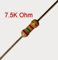
"Resistor"


"Connecting Wires"


 "Breadboard"


(Note: The color green for highlights tells that the holes there are connected together as one path. The holes in the sides are for connection to voltage terminals.)


"Digital Multimeter"


"Variable DC Power Supply "


Some Learnings:

  • In a series circuit, all components are connected end-to-end, forming a single path for electrons to flow.
  • In a parallel circuit, all components are connected across each other, forming exactly two sets of electrically common points.
  • When two resistors R1 = (1/G1) and R2 = (1/G2)  are in series, their equivalent resistance Req and equivalent conductance Geq are:

  •  When two resistors R1 = (1/G1) and R2 = (1/G2)  are in parallel, their equivalent resistance Req and equivalent conductance Geq are:


  •  The voltage division principle for two resistors in series is:
  •  The current division principle for two resistors in parallel is:


Video:

      For more information, you can watch the video below! :)


That's all. Thank You for visiting my blog.
GOD Bless! :)


By:
AYALA, ARNY  S.   BSECE -3
ECE 311
Professor:
ENGR. JAY S. VILLAN, MEP