Nodes, Branches and Loops:
What is node, branch and a loop in a circuit?
When we discuss
network topology we have to understand certain terms. Among these
terms node, branch or loops are used most of the time. Let’s see what they
mean.
Branch: A single element with its terminals is usually called a branch. For example a voltage source or a resistor is a branch.
Node: When two or more
branches are connected at a point then that point is called a node.
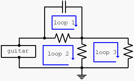
For some example let’s have look
at the following figure:
In a network or circuit, number of
loop, nodes and branches has to satisfy the following
fundamental relationship:
b=l+n-1
where, b = number of branches,
l = number of
loops and
n = number of nodes.
Kirchhoff's Circuit Law:
Ohm’s law by itself is not sufficient to analyze
circuits. However, when it is coupled with Kirchhoff’s two laws, we have a
sufficient, powerful set of tools for analyzing a large variety of electric
circuits. Kirchhoff’s laws were first introduced in 1847 by the German
physicist Gustav Robert Kirchhoff (1824–1887).
These laws are formally known as Kirchhoff’s current
law (KCL) and Kirchhoff’s voltage law (KVL). Kirchhoff’s first law is based
on the law of conservation of charge, which requires that the algebraic
sum of charges within a system cannot change.
- Kirchhoff’s current law (KCL) - states that the algebraic sum of currents entering a node (or a closed boundary) is zero.
Mathematically, KCL implies that,
Example,
The current entering any junction is equal to
the current leaving that junction. Therefore, i2 + i3 = i1 + i4 .
- Kirchhoff’s voltage law (KVL) - states that the algebraic sum of all voltages around a closed path(or loop) is zero.
Expressed mathematically, KVL states that,
Example,
The
sum of all the voltages around the loop is equal
to zero. Therefore, v1+ v2 + v3 - v4 = 0 .
to zero. Therefore, v1+ v2 + v3 - v4 = 0 .
Laboratory:
We are able to measure the resistance using it's color coding.
Some Learnings:
- From determining the nodes of the circuit, we can redraw it like the following figures:
We
demonstrate that the circuit has only three nodes by redrawing the circuit
:
- I also learned that two or more elements are in series if they are cascaded or connected sequentially and consequently carry the same current. And the two or more elements are in parallel if they are connected to the same two nodes and consequently have the same voltage across them.
- I learned to measure the resistance using the color coding but then, it is easier to use the digital multimeter than the color coding process.
Videos:
Watch the video below for more information:
That's all. Thank You for visiting my blog.
GOD Bless! :)
By:
AYALA, ARNY S. BSECE -3
ECE 311
Professor:
ENGR. JAY S. VILLAN, MEP


No comments:
Post a Comment