Saturday, October 11, 2014

Week Thirteenth: "First-Order Circuits"

What is a First-Order Circuits?


         Now that we have considered the three passive elements (resistors, capacitors, and inductors) and one active element (the op amp) individually, we are prepared to consider circuits that contain various combinations of two or three of the passive elements. In this chapter, we shall examine two types of simple circuits: a circuit comprising a resistor and capacitor and a circuit comprising a resistor and an inductor. These are called RC and RL circuits, respectively. As simple as these circuits are, they find continual applications in electronics, communications, and control systems, as we shall see.


         We carry out the analysis of RC and RLcircuits by applying Kirchhoff’s laws, as we did for resistive circuits. The only difference is that applying Kirchhoff’s laws to purely resistive circuits results in algebraic equations, while applying the laws to RC and RL circuits produces differential equations, which are more difficult to solve than algebraic equations. The differential equations resulting from analyzing RC and RL circuits are of the first order. Hence, the circuits are collectively known as first-order circuits.

         A first-order circuit is characterized by a first-order differential equation.


         In addition to there being two types of first-order circuits (RC and RL), there are two ways to excite the circuits. The first way is by initial conditions of the storage elements in the circuits. In these socalled source-free circuits, we assume that energy is initially stored in the capacitive or inductive element. The energy causes current to flow in the circuit and is gradually dissipated in the resistors. Although sourcefree circuits are by definition free of independent sources, they may have dependent sources. The second way of exciting first-order circuits is by independent sources. In this chapter, the independent sources we will consider are dc sources. (In later chapters, we shall consider sinusoidal and exponential sources.) The two types of first-order circuits and the two ways of exciting them add up to the four possible situations we will study in this blog.

         Finally, we consider four typical applications of RC and RL circuits: delay and relay circuits, a photoflash unit, and an automobile ignition circuit.


"The Source-Free RC Circuit"


         A source-free RC circuit occurs when its dc source is suddenly disconnected. The energy already stored in the capacitor is released to the resistors.


         Consider a series combination of a resistor and an initially charged capacitor, as shown in Figure below. 


         (The resistor and capacitor may be the equivalent resistance and equivalent capacitance of combinations of resistors and capacitors.) Our objective is to determine the circuit response, which, for pedagogic reasons, we assume to be the voltage v(t) across the capacitor. Since the capacitor is initially charged, we can assume that
at time t = 0, the initial voltage is


v(0) = Vo

with the corresponding value of the energy stored as


 Applying KCL at the top node of the circuit above, we get,

ic + iR = 0

By definition, iC = C dv/dt and iR = v/R. Thus,


But from the initial conditions, v(0) = A = V0. Hence,


         This shows that the voltage response of the RC circuit is an exponential decay of the initial voltage. Since the response is due to the initial energy stored and the physical characteristics of the circuit and not due to some external voltage or current source, it is called the natural response of the circuit.


         The natural response of a circuit refers to the behavior (in terms of voltages and currents) of the circuit itself, with no external sources of excitation.

         The time constant of a circuit is the time required for the response to decay by a factor of 1/e or 36.8 percent of its initial value.


τ = RC

In terms of the time constant, equation above will be,


Example:
~


"The Source-Free RL Circuit"

         Consider the series connection of a resistor and an inductor, as shown in Fig. below.


         Our goal is to determine the circuit response, which we will assume to be the current i(t) through the inductor. We select the inductor current as the response in order to take advantage of the idea that the inductor current cannot change instantaneously. At t = 0, we assume that the inductor has an initial current I0, or

i(0) = Io

with the corresponding energy stored in the inductor as


         This shows that the natural response of the RL circuit is an exponential decay of the initial current. The current response is shown in Figure below. 


The time constant for the RL circuit is,


Therefore we will have,


Example:


Some Learnings:

  1. First order circuit are circuits that contain only one energy storage element, a capacitor or an inductor.
    ~
  2. There are only two possible first order circuits, and that are RC (Resistor and Capacitor) & RC (Resistor and Inductor).
    ~
  3. The time constant is the same regardless of what the output is defined to be.
    ~
  4. When a circuit has a capacitor/inductor, a resistor and a dependent source. We use Thevenin's theorem and its equivalent can be found at the terminals of a capacitor or an inductor.


Videos:
~
For some information, you can watch the video below:


That's all. Thank You for visiting my blog.
GOD Bless! :)

By:
AYALA, ARNY  S.   BSECE -3
ECE 311
Professor:
ENGR. JAY S. VILLAN, MEP - EE


Saturday, October 4, 2014

Week Twelve: "Maximum Power Transfer, Capacitors & Inductors"


"Maximum Power Transfer"

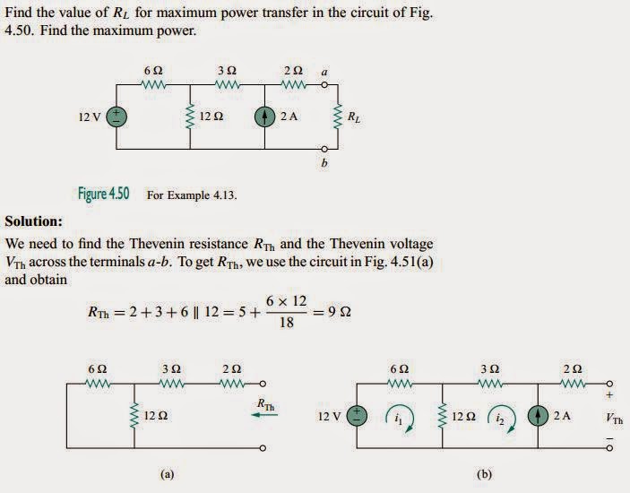
         In many practical situations, a circuit is designed to provide power to a load. While for electric utilities, minimizing power losses in the process of transmission and distribution is critical for efficiency and economic reasons, there are other applications in areas such as communications  where it is desirable to maximize the power delivered to a load. We now address the problem of delivering the maximum power to a load when given a system with known internal losses. It should be noted that this will result in significant internal losses greater than or equal to the power delivered to the load. The Thevenin equivalent is useful in finding the maximum power a linear circuit can deliver to a load. We assume that we can adjust the load resistance RL. If the entire circuit is replaced by its Thevenin equivalent except for the load, as shown in Fig. below, the power delivered to the load is
~


         Maximum power is transferred to the load when the load resistance equals theThevenin resistance as seen from the load (RL = RTh).


         Some important relations and equations are:


Example:


Capacitors:


         A capacitor is a passive element designed to store energy in its electric field. Besides resistors, capacitors are the most common electrical components. Capacitors are used extensively in electronics, communications, computers, and power systems. For example, they are used in the tuning circuits of radio receivers and as dynamic memory elements in computer systems.

         A capacitor consists of two conducting plates separated
by an insulator (or dielectric).

         In many practical applications, the plates may be aluminum foil while the dielectric may be air, ceramic, paper, or mica. When a voltage source v is connected to the capacitor, the source deposits a positive charge q on one plate and a negative charge −q on the other. The capacitor is said to store the electric charge. The amount of charge stored, represented by q, is directly proportional to the applied voltage v so that,

q = Cv  (Equation 1)

         Capacitance is the ratio of the charge on one plate of a capacitor to the voltage difference between the two plates, measured in farads (F).

         To obtain the current-voltage relationship of the capacitor, we take the derivative of both sides of Equation 1. Since

i = dq/dt

differentiating both sides of Equation 1 gives,

i = C (dv/dt)  (Equation 2)

         The voltage-current relation of the capacitor can be obtained by integrating both sides of Equation 2. We get


         We note that v(−∞) = 0, because the capacitor was uncharged at t = −∞. Thus,


         The voltage on a capacitor cannot change abruptly.


Example:

1.

2.


"Series - Parallel Capacitors"


         The equivalent capacitance of N parallel-connected capacitors is the sum of the individual capacitances.


Ceq = C1 + C2 + C3 ... + Cn
         The equivalent capacitance of series-connected capacitors is the reciprocal of the sum of the reciprocals of the individual capacitances.


Example:
~


"Inductors"


         An inductor is a passive element designed to store energy in its magneticfield. Inductors find numerous applications in electronic and power systems. They are used in power supplies, transformers, radios, TVs, radars, and electric motors. Any conductor of electric current has inductive properties and may be regarded as an inductor. But in order to enhance the inductive effect,
a practical inductor is usually formed into a cylindrical coil with many turns of conducting wire.

         An inductor consists of a coil of conducting wire.


         If current is allowed to pass through an inductor, it is found that the voltageacross the inductor is directly proportional to the time rate of change of the current. Using the passive sign convention,

v = L(di/dt)

         where L is the constant of proportionality called the inductance of the inductor. The unit of inductance is the henry (H), named in honor of the American inventor Joseph Henry (1797–1878). One henry is equals to 1 volt-second per ampere.


         Inductance is the property whereby an inductor exhibits opposition to the change of current flowing through it, measuredin henrys (H).

         The current-voltage relationship will be obtained as,


Since i(−∞) = 0,

         The current through an inductor cannot change instantaneously.


Examples:

1.

2.
3.


Some Learnings:
  1. The maximum power transfer can be obtain by letting RL eeual to Rth.
    ~
  2. Thevenin equivalent is a used in finding the maximum power.
    ~
  3. A capacitor is an open circuit to dc.
    ~
  4. Capacitors have the same voltages when they are connected in parallel the same with resistors.
    ~
  5. Capacitor is a passive two-terminal electrical component used to store energy.
    ~
  6. An inductor acts like a short circuit to dc.

Videos:

         For more information, you can watch the video below:

(Maximum Power Transfer)
(Capacitors)
(Inductors)


That's all. Thank You for visiting my blog.
GOD Bless! :)

By:
AYALA, ARNY  S.   BSECE -3
ECE 311
Professor:
ENGR. JAY S. VILLAN, MEP - EE


Week Eleven: "Thevenin's Theorem With Dependent Sources"


"Thevenin's Theorem" (With Dependent Sources)

CASE 2:


         If the network has dependent sources, we turn off all independent sources. As with superposition, dependent sources are not to be turned off because they are controlled by circuit variables. We apply a voltage source Vo at terminals a and b and determine the resulting current Io. Then Rth = Vo/ Io, as shown in Fig.(a) below. Alternatively, we may insert a current source Io at terminals a-b as shown in Fig. (b) below and find the terminal voltage vo. Again Rth = Vo/ Io. Either of the two approaches will give the same result. In either approach we may assume any value of Vo and Io. For example, we may use Vo = 1 V or Io = 1 A, or even use unspecified values of Vo or Io.


Example:

         Find the Thevenin equivalent of the circuit in Fig. 4.31.


Some Learnings:
~
  1. In getting the Rth, the same thing we apply with Case 1, we turn off the independent voltage sources by replacing an open circuit and independent current sources by closed circuit, then we replace an open circuit. We replace voltage or current independent source from terminal a to b and assume 1V or 1A on it.
    ~
  2. If there is no independent sources in a circuit, we can conclude that Vth is equal to zero.

Video:


For more information, you can watch the video below:


That's all. Thank You for visiting my blog.
GOD Bless! :)


By:
AYALA, ARNY  S.   BSECE -3
ECE 311
Professor:
ENGR. JAY S. VILLAN, MEP - EE


Week Ten: "Thevenin & Norton's Theorem"

What is Thevenin & Norton's Theorem?

"Thevenin's Theorem"


         It often occurs in practice that a particular element in a circuit is variable (usually called the load) while other elements are fixed. As a typical example, a household outlet terminal may be connected to different appliances constituting a variable load. Each time the variable element is changed, the entire circuit has to be analyzed all over again. To avoid this problem, Thevenin’s theorem provides a technique by which the fixed part of the circuit is replaced by an equivalent circuit.


         Thevenin’s theorem states that a linear two-terminal circuit can be replaced by an equivalent circuit consisting of a voltage source VTh in series with a resistor RTh, where VTh is the open-circuit voltage at the terminals and RTh is the input or equivalent resistance at the terminals when the independent sources are turned off.


CASE 1:


         If the network has no dependent sources, we turn off all independent sources. RTh is the input resistance of the network looking between terminals a and b, as shown below:


Example:


"Norton's Theorem"


         In 1926, about 43 years after Thevenin published his theorem, E. L. Norton, an American engineer at Bell Telephone Laboratories, proposed a similar theorem.


         Norton’s theorem states that a linear two-terminal circuit can be replaced by an equivalent circuit consisting of a current source In in parallel with a resistor Rn, where In is the short-circuit current through the terminals and Rn is the input or equivalent resistance at the terminals when the independent sources are turned off.


         The proof of Norton’s theorem will be given in the next section. For now, we are mainly concerned with how to get Rn and In . We find Rn in the same way we find Rth. In fact, from what we know about source transformation, the Thevenin and Norton resistances are equal; that is,


Rn = Rth
Thus,
In = Isc
          Dependent and independent sources are treated the
same way as in Thevenin’s theorem. Finding Norton
current In . Observe the close relationship between Norton’s and Thevenin’s theorems: Rn = Rth, and:


Example:

Some Learnings:


  1. If Rth takes a negative value. In this case, the negative resistance (v = −iR) implies that the circuit is supplying power.
    ~
  2. Thevenin’s theorem is very important in circuit analysis. It helps simplify a circuit.
    ~
  3. By Thevenin's theorem a large circuit may be replaced by a single independent voltage source and a single resistor. This replacement technique is very powerful in circuit design.
    ~
  4. If there is no independent sources in a circuit, we can conclude that Vth is equal to zero.
    ~
  5. Thevenin's Theorem & Norton's Theorem are related to each other.
    ~
  6. When getting for Rth or Rn, we turn off the voltage sources by replacing an open circuit and current sources by closed circuit. Then we replace an open circuit from terminal a to b.
    ~
  7. To find the Norton current In, we replace a short-circuit flowing from terminal a to b.


Videos:
For more information, you can watch the videos below:

(For Thevenin's Theorem)


(For Norton's Theorem)


That's all. Thank You for visiting my blog.
GOD Bless! :)


By:
AYALA, ARNY  S.   BSECE -3
ECE 311
Professor:
ENGR. JAY S. VILLAN, MEP - EE