"Maximum Power Transfer"
In many practical situations, a circuit is designed to provide power to a load. While for electric utilities, minimizing power losses in the process of transmission and distribution is critical for efficiency and economic reasons, there are other applications in areas such as communications where it is desirable to maximize the power delivered to a load. We now address the problem of delivering the maximum power to a load when given a system with known internal losses. It should be noted that this will result in significant internal losses greater than or equal to the power delivered to the load. The Thevenin equivalent is useful in finding the maximum power a linear circuit can deliver to a load. We assume that we can adjust the load resistance RL. If the entire circuit is replaced by its Thevenin equivalent except for the load, as shown in Fig. below, the power delivered to the load is
~
~


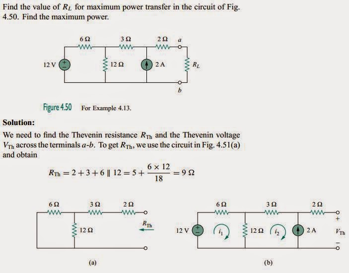
Maximum power is transferred to the load when the load resistance equals theThevenin resistance as seen from the load (RL = RTh).
Some important relations and equations are:


Example:

Capacitors:

A capacitor is a passive element designed to store energy in its electric field. Besides resistors, capacitors are the most common electrical components. Capacitors are used extensively in electronics, communications, computers, and power systems. For example, they are used in the tuning circuits of radio receivers and as dynamic memory elements in computer systems.
A capacitor consists of two conducting plates separated
by an insulator (or dielectric).
In many practical applications, the plates may be aluminum foil while the dielectric may be air, ceramic, paper, or mica. When a voltage source v is connected to the capacitor, the source deposits a positive charge q on one plate and a negative charge −q on the other. The capacitor is said to store the electric charge. The amount of charge stored, represented by q, is directly proportional to the applied voltage v so that,
q = Cv (Equation 1)
Capacitance is the ratio of the charge on one plate of a capacitor to the voltage difference between the two plates, measured in farads (F).
To obtain the current-voltage relationship of the capacitor, we take the derivative of both sides of Equation 1. Since
i = dq/dt
differentiating both sides of Equation 1 gives,
i = C (dv/dt) (Equation 2)
The voltage-current relation of the capacitor can be obtained by integrating both sides of Equation 2. We get

We note that v(−∞) = 0, because the capacitor was uncharged at t = −∞. Thus,

The voltage on a capacitor cannot change abruptly.
Example:
Example:
1.

2.

"Series - Parallel Capacitors"
The equivalent capacitance of N parallel-connected capacitors is the sum of the individual capacitances.
Ceq = C1 + C2 + C3 ... + Cn
The equivalent capacitance of series-connected capacitors is the reciprocal of the sum of the reciprocals of the individual capacitances.

Example:
~
~

"Inductors"

An inductor is a passive element designed to store energy in its magneticfield. Inductors find numerous applications in electronic and power systems. They are used in power supplies, transformers, radios, TVs, radars, and electric motors. Any conductor of electric current has inductive properties and may be regarded as an inductor. But in order to enhance the inductive effect,
a practical inductor is usually formed into a cylindrical coil with many turns of conducting wire.
An inductor consists of a coil of conducting wire.
If current is allowed to pass through an inductor, it is found that the voltageacross the inductor is directly proportional to the time rate of change of the current. Using the passive sign convention,
v = L(di/dt)
where L is the constant of proportionality called the inductance of the inductor. The unit of inductance is the henry (H), named in honor of the American inventor Joseph Henry (1797–1878). One henry is equals to 1 volt-second per ampere.
Inductance is the property whereby an inductor exhibits opposition to the change of current flowing through it, measuredin henrys (H).
The current-voltage relationship will be obtained as,

Since i(−∞) = 0,

The current through an inductor cannot change instantaneously.
Examples:
1.

2.

3.

Some Learnings:
- The maximum power transfer can be obtain by letting RL eeual to Rth.
~ - Thevenin equivalent is a used in finding the maximum power.
~ - A capacitor is an open circuit to dc.
~ - Capacitors have the same voltages when they are connected in parallel the same with resistors.
~ - Capacitor is a passive two-terminal electrical component used to store energy.
~ - An inductor acts like a short circuit to dc.
Videos:
For more information, you can watch the video below:
(Maximum Power Transfer)
(Capacitors)
(Inductors)
That's all. Thank You for visiting my blog.
GOD Bless! :)
By:
AYALA, ARNY S. BSECE -3
ECE 311
Professor:
ENGR. JAY S. VILLAN, MEP - EE
No comments:
Post a Comment